This is a General Guide to HVAC Troubleshooting.
We won’t be getting into specifics that involve local codes, OEM procedures and guidelines or in-depth analysis of things like static pressure, superheat or sub-cooling.
But, it is imperative as a technician that you understand basic refrigeration/heating and electrical fundamentals to carry out a proper diagnosis safely.
If you are currently learning the basic principles, I highly recommend that you communicate with a senior technician during your service, if that luxury is available or get involved with the strong technician culture on the subscription-based HVAC Know It All app.
This article will focus on some hurdles that must be crossed before the next step of troubleshooting can take place.
Technicians should consider themselves skilled trade detectives, gathering info from various places.
Some service calls take a few minutes; some can take several hours or days, depending on the complexity of the problem.
✅ PRO TIP: Before we begin troubleshooting, ensure that the appropriate PPE (personal protective equipment) is put into place, including safety glasses, gloves, etc.
This article is complemented by a podcast episode discussing HVAC/R service. Listen on the HVAC Know It All Podcast
Diagnostic Tools
To carry out a diagnosis of any system, there are tools that will be needed during the process.
One or a combination of the tools below will help you create a big-picture snapshot of the problem at hand; let’s go through them individually.
Manifold Gauges
A compound set of manifold gauges are used to test the system pressures of an air conditioning or refrigeration system.
They also give you an indication of the saturated temperature for each refrigerant.
If your manifold gauge does not include a scale for the refrigerant you are working on, you will need to utilize a pressure/temperature chart for that particular refrigerant.
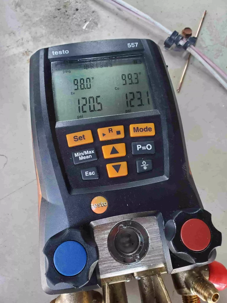
Another option is using a digital apparatus in the form of a manifold set or smart probes.
Digital gauges implement pressure/temperature charts within and can be read on the display screen or they are calculated using a mobile application.
This video explains how to check evaporator superheat using smart probes:
Temperature Probe or Clamp
To check superheat and subcooling of a system, you will need a temperature sensing device that can be mounted on the refrigerant lines of the system.
Multi Meter
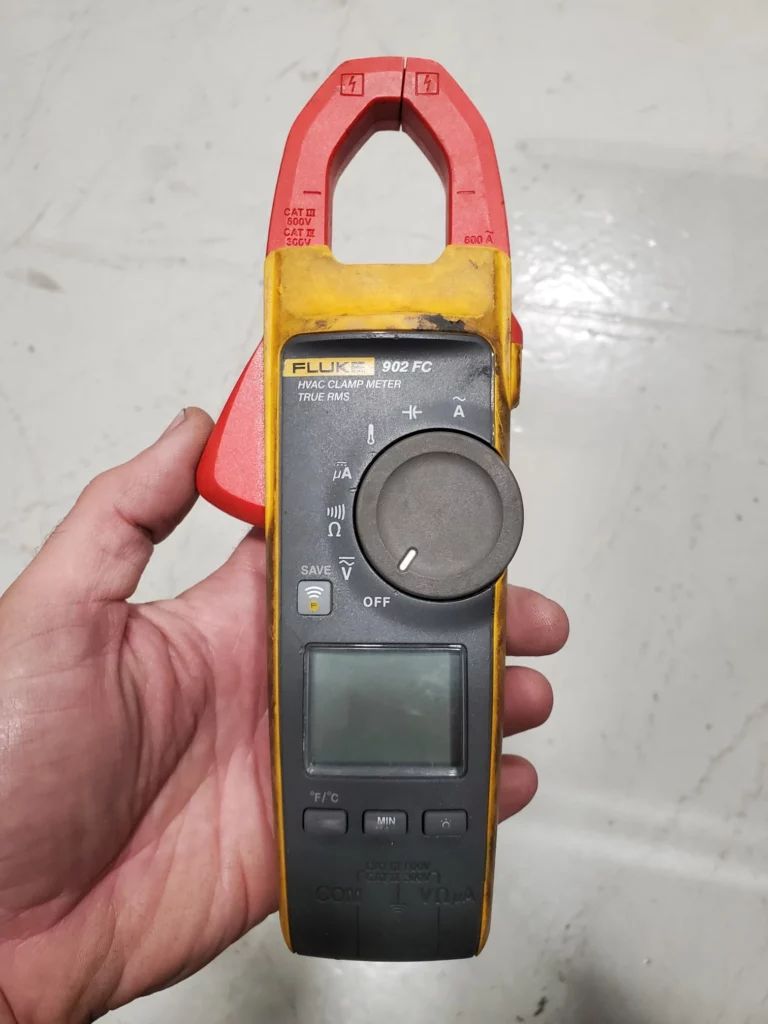
A good multimeter will be used the most on any given service call, as most problems are related to electrical issues.
A multimeter or combination of meters should be able to check AC/DC voltage, amp draw, resistance in the Ohm setting, capacitor microfarads, and DC microamps of a flame sensor for basic troubleshooting purposes.
Check out the video testing flame signal using DC microamps.
Also, check out the video troubleshooting a walk-in cooler condensing unit using different meter functions:
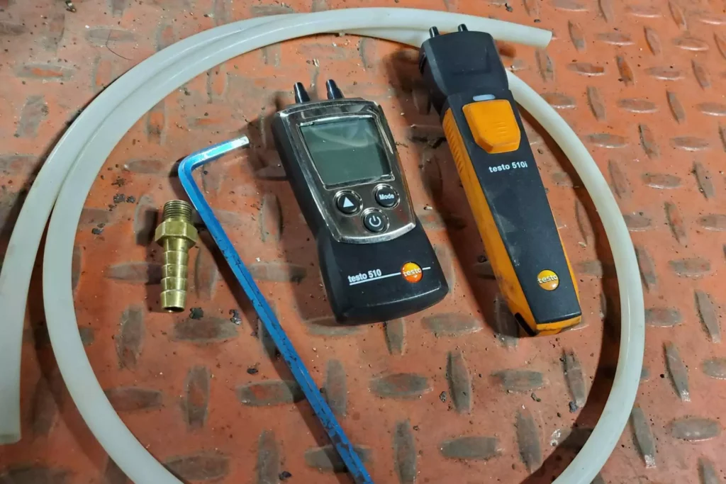
Dual Port Manometer
A manometer serves a few functions like checking the gas pressure of a heating appliance, differential pressure across coils and filters, and checking static pressure of duct systems.
Present-day manometers allow for options; we can choose a manometer with a display screen or a manometer that links to a mobile device via Bluetooth.
Here are two videos displaying both types in action in the field https://youtu.be/tsLgkRaEyBY and https://youtu.be/a5SR4Ys6Fsk.
Electronic Refrigerant Leak Detector
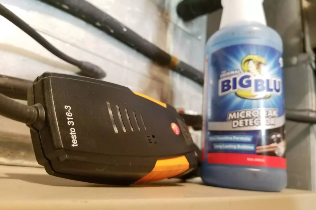
To find leaks within a refrigeration system effectively and quickly, a quality electronic leak detector can be used to do so.
It is important to use a combination of an electronic leak detector and soap to verify the presence of a refrigerant leak.
This article explains in detail the procedure: Refrigerant Leak Checking Procedure
Hygrometer
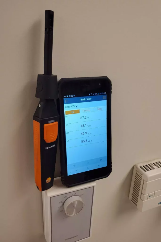
A hygrometer measures temperature and humidity and can give readings like wet bulb temperature and dew point, depending on the brand.
This is a useful tool to check outside and indoor air conditions and supply air and return air.
Checking room conditions using a digital smart probe and mobile app.
Some other tools to note that are used for diagnostic purposes include:
• Combustion Analyzer
• Infrared Temperature Gun
• Thermal Imager
• Rotating Vane or Hot Wire Anemometer
Sequence of Operation
Before diving into the steps of approaching and working through a service call, we need to understand the equipment sequence of operations, what happens first, and then what happens next.
For an example of a sequence of operations, we will use a residential furnace.
1. A call for heat is made from the thermostat.
2. The induced draft motor starts and air flow within the combustion chamber must be proved by a pressure switch. The induced fan runs a timed pre-purge of the burner and venting.
3. The ignition control is powered, providing that all safety switches are closed.
4. The means of ignition is enabled (spark or hot surface ignitor), the gas valve opens, the burner lights and ignition must be proved.
5. The burner stays lit, and the blower fan starts after a time delay to allow heat the exchanger to warm up.
6. The thermostat satisfies and the burner shuts off after the gas valve is powered down.
7. The induced fan motor runs a post purge of the burner and venting.
8. The blower fan runs a timed cool down of the heat exchanger.
Check out this video moving through the steps of a no heat call.
It’s important to understand that many types of equipment may utilize different sequences.
It’s your job as the technician to know this before proceeding.
Using manuals and/or tech support can be a good place to obtain this info.
✅ PRO TIP: Understanding wiring diagrams is essential to troubleshooting and understanding sequence of operations. It is advised you become an expert at reading and comprehending wiring diagrams to troubleshoot safely and effectively.
General Troubleshooting Steps
Step One: Customer Communication
If possible, reach out to the customer before heading out, have them explain to you what is happening, and possibly have them record a video or take a picture from a distance for you to reference when you arrive on site.
NOTE: Do not ask a customer to go beyond this. For example, don’t have them open panels, reset limits, etc. Don’t put your customer’s safety at risk.
Once en route, “DO NOT” create scenarios in your head of what might be wrong.
Too many fall into the trap of pre-diagnosing equipment before arrival and immediately attempt to prove their guess is correct.
Instead, use a methodical approach, and start from the beginning to ensure nothing is missed.
Crank up the radio or listen to the HVAC Know It All Podcast 😉 and keep your mind free and clear.
Once you arrive, analyze any info the customer has gathered for you.
Find out how long the issue has been present when it happens, where it happens, etc. this will help you form a pattern of the potential issues.
If the customer has access to archived trend logs that show ambient temperature/humidity or supply air temperature, for example, ask to see it!
✅ PRO TIP: DO NOT accept a customer’s diagnosis of the issue. You are the professional, and it’s your job, not theirs, to troubleshoot.
Step Two: Inspect Using Your Senses
Note: Before entering a mechanical room, crawl space, basement or attic where gas, propane or oil-fired equipment is being used… consider wearing a personal carbon monoxide monitor to ensure your safety.
Before using any diagnostic tools, visually inspect the equipment, and look for obvious things that can be rectified before continuing.
For example, a dirty condenser coil, loose or faulty wiring connections or improper venting.
We can take this a bit further to include other senses like listening for odd sounds, smelling for burnt windings, using our hands to feel for vibration or to get an indication of pipe temperature.
As a reference, the palm of a human hand is roughly 92⁰ Fahrenheit. Anything that feels warmer than your hand is warmer than 92⁰F, and the opposite remains true.
✅ PRO TIP: Before reaching into unit cabinets, ensure power has been disconnected and verified with a multimeter and lock-out tag out where necessary.
Step Three: Verifying Power
After the initial inspection of the equipment, we must look at our primary power source.
Without the correct power, we can’t move forward.
If power is not present, inspect the power source for a tripped breaker or open fuse.
If for example, the breaker is tripped, we may have a short within the wiring or primary load within the appliance.
This must be rectified before proceeding.
NOTE: An example of a primary load is a motor or compressor that accepts power from the primary source that is fed to the equipment. For example, a condensing unit’s primary power might be 208/230, which is fed directly from the breaker panel.
✅ PRO TIP: Before restoring power at the main source (breaker or fuse panel), ensure the local disconnect is off at the appliance.
If the breaker trips or fuses blow when re-applying main power, we have ruled at the appliance being the root cause.
Once primary power has been restored and is correct, we need to verify the presence of control voltage or secondary voltage.
Control voltage can exist in many forms, for example, 24v, 120v, 208/230v and is usually fed from a step-down transformer. For this article, we will assume 24v.
✅ PRO TIP: If you are dealing with primary power issues (breaker tripping when equipment begins to run).
It is recommended to pull the “R” wire from the appliance low voltage terminal strip until the issues are resolved.
This will prevent equipment from trying to start up during the troubleshooting process.
Now that we have confirmed that the primary and secondary power sources are correct, we must check our method of control.
This could be a simple thermostat or a slightly more complicated building automation system.
Ensure the controller is powered up, functional and set correctly.
✅ PRO TIP: Faulty thermostats can sometimes be diagnosed by bypassing them.
For example, if the thermostat is calling for cooling and the display indicates a call, but the equipment hasn’t started, pull the thermostat from the sub base and short (jump out) “R” and “Y1” at the sub base.
This test removes the thermostat from the equation.
If the equipment starts up, in most cases, the thermostat has failed.
Step Four: Heat Exchange Medium
If we have improper airflow, we can not exchange heat as the system is designed to do.
The same lies true for flow of water/glycol.
The only difference is air uses a fan, and fluid uses a pump.
We must ensure we have the correct air flow or fluid flow before the next step of troubleshooting can take place.
Ensure the fan or pump is powered, running and, most importantly, rotating in the correct direction.
Make sure air filters and inline strainers are clean.
In worst-case scenarios, system balancing may need to take place to obtain the correct flow.
Until we can prove the correct flow of our heat exchange medium, it is a good idea to keep the system off regarding heating or cooling.
✅ PRO TIP: If the fan or pump does not start on a call, further troubleshooting will need to be done.
For example, checking incoming power to the load and ensuring it is correct, checking capacitors if utilized and relays or contactors.
If the pump/fan is found to be faulty, it must be changed before proceeding.
✅ PRO TIP: If the system uses a relay board, you will need to ensure the board is receiving an input (a call) and, conversely, relaying an output signal.
In many cases, if the board is receiving an input and not providing an output, under normal circumstances, the board is usually defective and will need replacing.
Step 5: Full System Diagnoses
We have received info from the customer, rectified visual defects, ensured the correct power and call for heating or cooling and ensured flow of our heat exchange medium.
What’s next? For this example, we will concentrate on a cooling diagnosis.
We have a call for cooling, and the compressor/condenser fan contactor does not pull in. What’s next?
- Inspect the safety circuit for any open switches. For example, open low or high pressure switches will hold up the flow of power to the contactor coil. Also, some units may utilize interlock circuits to ensure a pump or fan has started, an interlock is usually a normally open contact that closes once flow is proved.
✅ PRO TIP: If the pump or fan is running and you have determined flow is correct, but the heating or cooling won’t engage, the interlock switch may be stuck open if it has one.
- If the safety switches and interlocks are closed, and the compressor/fan contactor receives 24v across the coil, but the contactor will not pull in, verify that the contactor coil is not open or defective.
✅ PRO TIP: Our multi-meter on the ohm setting is used to check winding resistance. If the meter reads OL across the coil, the coil is open and defective.
✅ PRO TIP: If the low voltage common is lost or broken within the circuit. Each side of the contactor coil will read 24v to ground with a multimeter on the volt setting. The broken common must be rectified before moving on.
The compressor/condenser fan contactor pulls in and nothing happens, what’s next.
- Ensure that the correct power is passing through the contactor to each load. For example, if the compressor is 208V, ensure it is receiving 208V.
✅ PRO TIP: On a single phase system, the C (common) and R (Run) terminals on the compressor are where the primary voltage is provided and checked by applying your meter leads across them. On three-phase systems, you must check across T1-T2, T1-T3 and T2-T3 and have the correct primary voltage on all three phases.
- Check capacitor MFD’s and start components for any defects.
✅ PRO TIP: If the run and start windings are reversed on the capacitor, it can cause the motor to turn in the opposite direction.
- Check motor windings to ensure they are not open. Keep in mind that a shorted winding may, in fact trip the breaker or cause a fuse to blow.
✅ PRO TIP: If any components are found to be defective at this point, we must replace them before continuing.
The compressor and condenser fan motor start once powered. What’s next?
- Check amp draw of each component to ensure it’s within it’s name plate rating.
- Check system performance using gauges, check system saturated condensing temperature, saturated suction temperature, superheat and sub-cooling and ensure they fall into the design parameters of the system.
✅ PRO TIP: If using digital gauges such as a Testo 550 or Smart Probes, they link to the measureQuick app. measureQuick can perform a non invasive test without the need for checking pressures or can also help diagnose a system by generating targets that must be met.
There are many other apps and tools available to help with system diagnoses.
A good service technician will stay open-minded and use the tools that are available to them.
It’s important to understand that assuming an outcome won’t work, we must verify through testing and come to the correct conclusion.
An unverified diagnosis will lead to a stressful visit to the parts counter, as you are guessing or making an assumption about the problem.
In Summary
Remember, this is a general guide to HVAC service.
You will have to put in the work and obtain the knowledge to carry out these tasks.
To summarize the article:
- Technicians should consider themselves skilled trades detectives.
- Basic and advanced diagnostic tools will help with a big-picture diagnosis.
- Understanding the sequence of operations and wiring diagrams is a must.
- Steps to a service call include customer communications, inspection with the senses, proper power, correct flow of heat exchange medium, and final diagnosis. Make sure the diagnosis is verified.
If you’re considering entering the HVAC/R trades or you’re an apprentice or helper, check out this video to provide some helpful motivation.
Good luck and happy HVACing!

