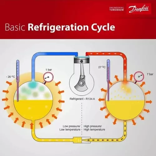
The Refrigeration Cycle Explained
To set this up properly, I really should bring up the first time I put some lackadaisical thought into refrigeration or air conditioning.
I was a young teen walking by the side of my home on a hot summer day; we had a power-draining, inefficient beast of a window unit that intrusively hung out the side of the house, almost obstructing the walkway.
It was outputting some major heat energy, and water was dripping from the back onto the ground.
I walked into the house, and it was cooler and less humid than it was outside.
Yes, I had an epiphany: Was the heat source I felt coming from the gargantuan brown box actually being drawn from my home, and was the dripping water being somehow siphoned from the indoor air and being transferred outdoors?
I knew this had to be true, but this was pre-internet or the internet as we now know it today, and the info I needed wasn’t readily available.
It wasn’t until years later, in trade school, that I learned that my theory was indeed correct.
Before we get started, if you’re looking for a professional online environment to discuss the trade, check out the subscription-based HVAC Know It All app.
The Refrigeration Cycle is a science; knowing it and knowing it well is a gift and a curse.
Gift, as we service techs know, it is our bread and butter, the way we make a living and provide for our families.
A curse, yes; as we service techs know, when it gets hot outside, everyone and their brother-in-law wants or needs a favor.
To understand the refrigeration cycle, we need to understand how refrigerant acts within a system.
We also need to understand how refrigerant reacts when its surrounding temperature changes as it pertains to its pressure.
After reading this article, check out this video explaining the refrigeration cycle with a more visual experience
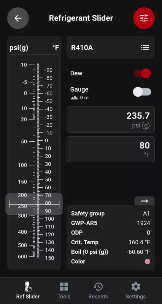
Let’s take R410a, a popular refrigerant at the moment and look at its saturated temperature at 72⁰F.
Notice the pressure on the Danfoss RefTools Refrigerant Slider is 207.7 PSI.
If we increase the saturated temperature of the same refrigerant to 80⁰F, the pressure increases to 235.7⁰F.
The first lesson here is that refrigerant pressure increases with a temperature rise, and conversely, refrigerant pressure decreases with a temperature drop.
I mentioned saturated temperature in the paragraph above, so let’s look at that and consider it lesson number two.
Saturation is essentially the refrigerant’s boiling point, where it is a liquid and a vapor at the same time.
As you can see from the above images on the Refrigerant Slider, R410a at atmospheric pressure boils at -60.60⁰F.
Let’s compare this to a boiling point of water.
Water at sea level will boil at 212⁰F, (100⁰C) once the water reaches its boiling point, it is a liquid (within the pot) and vapor (hovering above the liquid inside the pot) at the same time.
The water is at its saturated or boiling temperature.
Using water as an example usually helps to understand this concept.
But, water also follows the rules of the pressure/temperature relationship as well.
Water will boil at room temperature in a vacuum at 29.92″ hg (inches of mercury).
By placing a glass of water in an enclosed environment and then slowly decreasing the pressure within that environment by creating a vacuum, the water will boil, but at room temperature, that’s right, it’s not hot.
This is an exercise that many HVAC/R instructors use to showcase that pressure and temperature are related.
Just like with refrigerant, as we drop the pressure, we drop the saturated or boiling temperature of the water.
This usually starts the wheels in motion for many students.
Check out this experiment at home boiling water at room temperature in a vacuum.
We can’t move on until we speak briefly about superheat and sub-cooling.
These are vital factors to understanding the refrigeration cycle and what is happening within a system.
Superheat and sub-cooling are often used to diagnose systems and to dial in the refrigerant charge.
Superheat in a Refrigeration System
Simply put, superheat is anything above the saturation point.
Superheat ensures the substance is 100% vapor.
If we take R410a again as our example and we look at its saturation temperature at 118 PSI, it corresponds to 40⁰F.
This is a common pressure/temperature relationship pertaining to an evaporator for comfort cooling.
We sometimes refer to this as the saturated suction temperature or SST.
If we were to take an actual temperature of the suction line and it was measured at 50⁰F, our superheat would be calculated at 10⁰F.
Actual line temp 50⁰F – SST 40⁰F = Superheat 10⁰F
As we will touch on later, superheat in the suction line is needed to ensure only vapor enters the compressor during a running cycle.
This short video explains how to check evaporator superheat
Sub-Cooling in a Refrigeration System
Sub-cooling is the opposite of superheat, it is anything below the saturation point or boiling temperature.
Sub-cooling ensures the substance is 100% liquid.
A common saturated condensing temperature in comfort cooling is in the range of 100⁰F-110⁰F.
Let’s stick with 100⁰F for this example.
Using R410a again, a saturated condensing temperature or SCT of 100⁰F corresponds to 317 PSI.
By taking the actual temperature of the liquid line and receive a reading of 90⁰F, our sub-cooling for this example is 10⁰F.
SCT 100⁰F – Actual Line Temp 90⁰F = 10⁰F
Sub-cooling is needed in the liquid line to ensure our metering device receives a full column of liquid.
The Four Components
The refrigeration cycle can not take place without the following vital components.
Understand that many bells and whistles can be thrown into the mix as far as additional items within a circuit, but for now we will focus on the four major pieces of the puzzle.
1) Compressor
Compressors come in many shapes, sizes and types, but they all share the same role of facilitating the movement of refrigerant through a system.
When the compressor is powered, its job is to take low pressure, low-temperature refrigerant vapor from the suction line and compress it into a high-pressure, high-temperature refrigerant vapor into the discharge line.
Compressors are designed to move vapor through a system, not liquid.
Any liquid refrigerant that enters the compressor can cause damage and compressor failure.
Most compressors contain oil, the oil must be compatible with the type of refrigerant the system is utilizing.
The oil moves through the system with the refrigerant and keeps the compressor and system parts lubricated.
The liquid refrigerant inside a compressor can wash away compressor oil, causing internal parts to fail.
Common Types Of Compressors Are:
- Scroll
- Reciprocating
- Rotary
- Screw
The term semi-hermetic simply indicates the compressor is not fully sealed and can be taken apart for service.
A fully hermetic compressor or tin can, as it’s sometimes referred to, is a fully sealed unit and can not be field serviced.
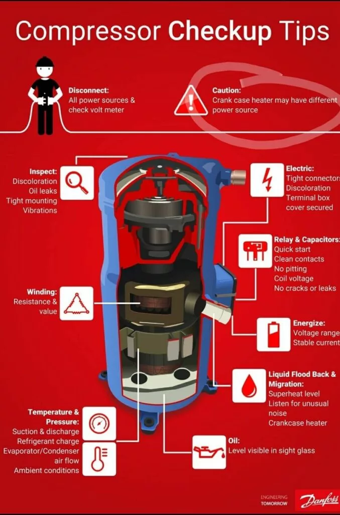
This is a great compressor check-up list from Danfoss Cool
2) Condenser
The condenser is a heat rejection device.
The refrigerant system picks up heat in the evaporator and also from the heat of compression (from the compressor itself), and the condenser rejects or rids the heat.
A condenser can be air-cooled by using a fan to move air across the coil and fins or water-cooled by using a pump to move water through a coaxial coil, brazed plate heat exchanger, or condenser bundle.
Because the condenser receives superheated refrigerant vapor from the discharge line, its first job is to cool the gas by de-superheating it.
Once the refrigerant reaches its saturated or boiling temperature, the condenser’s next job is to sub-cool the refrigerant.
This ensures that as the refrigerant leaves the condenser down the liquid line, a full column of liquid is making its way toward the metering device.
Common Types Of Condensers Are:
- Traditional copper coil with aluminum fins
- Micro Channel
- Condenser Bundle
- Coaxial Coil
- Brazed Plate Heat Exchanger
3) Metering Device
A metering device can be adaptive, such as a thermal expansion valve or fixed, such as a capillary tube or fixed orifice. Its job is to meter the sub-cooled liquid into the evaporator.
The metering device separates the system from the high-pressure side and the low-pressure side.
As the sub-cooled liquid passes through the metering device, it creates a flash gas.
This means a portion of the liquid is immediately turned or flashed into a vapor due to the drop in pressure.
A rule of thumb is 75% liquid and 25% vapor entering the evaporator.
To Dig a bit deeper into metering devices, check out this article.
Common Types Of Metering Devices
- Thermal Expansion Valve
- Automatic Expansion Valve
- Capillary tube
- Fixed orifice
- Electronic Expansion Valve stepper motor
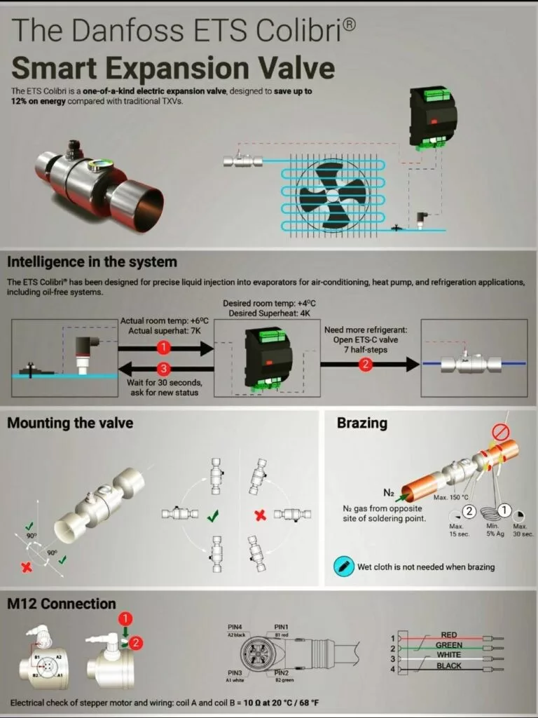
The future of metering refrigerant
Before we talk about the fourth major component, we should briefly discuss sensible and latent heat and the differences between them.
Sensible Heat
Sensible heat is the heat required to change the temperature of a substance.
For example, if we take 80⁰F air and remove 10⁰F so that air is now 70⁰F, we have done 10⁰F of sensible heat removal.
The temperature viewed on a standard thermostat display is an example of a change in sensible heat.
Latent Heat
Latent heat is the heat required to change the state of a substance.
By changing state, we mean changing water to a vapor or water vapor back to a liquid, for example.
4) Evaporator
Ah, for me, this is where the magic happens.
The evaporator’s job is to absorb heat and remove moisture from the air passing over it if we are speaking in terms of a standard evaporator coil.
A standard coil removes latent heat and sensible heat from the air passing by.
Latent heat removal is responsible for removing moisture or humidity from the air.
As the humid air comes into contact with the cold coil, water vapor clings to it, and the vapor changes state from a vapor to a liquid, known as condensation.
The condensation is collected in the evaporator drain pan and exits via a drain line.
Once the latent heat is removed (moisture from the air), sensible heat removal is able to take place at a greater pace.
Sensible heat removal, as previously discussed, is responsible for dropping the temperature of the air.
In chiller systems, the evaporator absorbs heat but not moisture, air does not pass over this type of evaporator.
Chillers use an evaporator bundle, refrigerant and water or glycol enter the bundle and heat is exchanged.
Chiller bundles can only perform sensible heat removal.
For this example, we will focus on a standard air over coil.
As the refrigerant enters the evaporator through the metering device, the pressure and temperature are reduced.
From our rule of thumb above, we used a mixture of 75% liquid and 25% vapor entering the evaporator.
The remaining liquid is boiled off as it absorbs the heat from the air passing over the coil.
In theory, all of the liquid is boiled off in the evaporator; any added heat after boiling is additional, and that additional heat is known as super heat.
Superheat ensures that only refrigerant vapor leaves the evaporator and enters the suction line.
The compressor brings back the superheated vapor and re-begins the refrigeration process.
Common types of evaporators are:
- Finned Evaporator (A coil and N coil)
- Evaporator bundle
- Plate evaporator
- Bare Tube
Check out a short podcast episode explaining refrigeration cycles.
The Refrigeration Cycle
Now that we have hammered down the major refrigeration cycle components, let’s put the refrigeration cycle together as one.
On call for cooling or refrigeration, the compressor starts.
The compressor, acting as a pump, will pressurize vapor refrigerant into a high-pressure high-temperature gas into the discharge line.
The vapor refrigerant in the discharge line is superheated.
The discharge line feeds refrigerant into the condenser.
As the refrigerant moves through the condenser, the refrigerant gas is cooled to remove the superheat.
The refrigerant moves into a saturated state (liquid and vapor at the same time) once it is de-superheated.
At this point, further heat is removed, and the refrigerant becomes a sub-cooled liquid as its temperature is now below its boiling or saturation point.
The sub-cooled liquid enters the liquid line.
At this point, still at high pressure but reduced temperature.
The sub-cooled liquid moves through the metering device, dropping its pressure and temperature as it flashes into the evaporator.
As air passes over the evaporator coil, the refrigerant absorbs heat.
The absorbed heat causes the refrigerant to reach its saturation or boiling point.
The refrigerant continues to absorb heat past its saturation point, the additional heat superheats the vapor.
The superheated vapor enters the suction line and returns to the compressor for the refrigeration cycle to repeat itself.
Key Points
- The compressor acts as a vapor pump to move refrigerant around the system. A compressor is not designed to pump liquid.
- The condenser rejects heat picked up from the system (evaporator and compressor) and is responsible for ensuring that the refrigerant leaving is a sub-cooled liquid.
- The metering device regulates high-pressure liquid refrigerant into the evaporator lowering the temperature and pressure. It is flashed into the evaporator as 75% liquid and 25% vapor as a rule of thumb.
- The evaporator absorbs heat from air in a home, for example, boiling off the remaining liquid refrigerant. The refrigerant picks up additional heat, the added heat is known as superheat. The superheated vapor moves into the suction line and back to the compressor.
Additional Components
As we have covered the four major components, a few additional components are important within a system we will cover as bonus material.
Pressure Switches
At a minimum, systems should be outfitted with high and low-pressure switches to protect the compressor.
We could discuss many safety switches, but high and low pressure cut out is super important to any system.
High Pressure Switch
The high-pressure switch can be found on the discharge line or the liquid line of any given system, it can also be mounted directly on the head of a semi-hermetic compressor.
It monitors the system pressure and will shut down the compressor on a high-pressure event.
High-pressure events can be caused by a dirty condenser coil, defective condenser fan and over charge, for example.
The setting of the high-pressure switch can be adjustable or fixed depending on the style of switch that is utilized.
The setting of the switch is dependent upon the refrigerant being used.
Not all refrigerants produce the same high side pressure and require different settings.
I have found that the cut-out setting usually sits in the range of 140⁰F to 155⁰F saturated condensing temperature or SCT.
If you look at the pressures that fall into that temperature range for any given refrigerant, it’s usually a good reference point for high-pressure cut-out.
Low Pressure Switch
The low-pressure cut-out switch is mounted on the suction line or even sometimes on the compressor body, as in the case with some semi-hermetic compressors.
Just as the high-pressure switch, low-pressure switches can be fixed or adjustable.
Also, again, the switch setting is dependent upon the refrigerant and application.
Low-pressure switches in comfort cooling are usually set around or above a pressure that corresponds to freezing.
For instance, R410a at 32⁰F saturation corresponds to a pressure of 101.6 PSI.
To protect the system from freezing up, the switch setting will need to be set in and around 101.6 PSI.
When speaking in regards to refrigeration, the low pressure switch is usually set up to shut down the system when it reaches set point or after a pump down.
The setting will be based on the site-specific application and refrigerant being used and may require some thought.
Low-pressure switches, in general, will also protect the system in a low charge situation.
If, for example, the system had a leak and lost its charge, the low-pressure switch would open up and not allow the compressor to run.
Liquid Line Filter Drier
A liquid line filter drier is a very important accessory to most systems.
It is installed in the liquid line as close to the metering device as possible.
Its job is to filter out any debris within a system and remove trace amounts of moisture that might be present using a desiccant material.
Liquid Line Sight Glass
A sight glass is an inline device that is also installed in the liquid line downstream (after) the filter drier.
It gives an indication that a full column of liquid is presently entering the metering device and also has a moisture indicator that changes color in the presence of moisture within a system.
A liquid line sight glass can also give indications that there is a problem in a system.
Receiver
A receiver is a storage device that stores refrigerant in the off-cycle after a pump down or stores refrigerant until it’s needed.
An example of this is winter operation, in cold ambient temperatures, more refrigerant is needed to pressurize the system.
The refrigerant would be stored in the receiver in warmer ambient temperatures, and as the ambient begins to drop, stored refrigerant is utilized to maintain system pressure.
Liquid Line Solenoid Valve
A liquid line solenoid valve is another inline component that is installed in the liquid line.
It is used in most cases to pump down a system.
When the valve is forced closed, the compressor continues to run; the refrigerant is pumped into the condenser/receiver.
As the evaporator and suction line pressures drop, the low-pressure switch will open cutting operation to the compressor.
When the valve is opened during a call, the evaporator and suction line are pressurized by an inrush of refrigerant.
The low-pressure switch closes, and the compressor re-initiates operation.
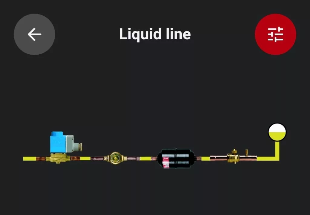
This image from the Danfoss RefTools App Troubleshooter shows a liquid line filter drier, sight glass and solenoid valve in series with flow moving from right to left.
This is a great animation from Danfoss to show how the pump down cycle work
The refrigeration cycle is a science that involves many factors and variables.
Knowing the refrigeration cycle well will ensure air conditioner success during service, installation, and maintenance.

